
In this video I replace the wheel bearings, brake discs and pads, and rebuild the calipers. This in-depth video covers each step of taking all the parts off the van and refitting new parts to the correct specification. Warning: As this video deals with critical brake systems it should not be used as a technicalContinue reading "Front Brakes and Wheel Bearings"
Ball Joint Replacement

In this video I remove and fit new upper, lower and tie rod end ball joints. I use a range of techniques (which includes a large hammer) and find you don't need the VW special tool to press anything in. https://youtu.be/4Igdi8tZLDo Difference in ball joint quality I went for Lemförder parts as they seem toContinue reading "Ball Joint Replacement"
Upper Control Arm Bushing Replacement

In this video I replace the bushings in the Upper Control Arm/Wishbone. I take all the parts off, do some spot welding, then refit and adjust to the correct specification. https://youtu.be/clnV764LBNU Welding for the first time I used a Clarke 151 TE Turbo Gas Mig Welder for the spot welds. I found the Mig WeldingContinue reading "Upper Control Arm Bushing Replacement"
Shock Absorber Damper Replacement

In this video I remove the original front and rear shock absorbers on my Volkswagen T25 and replace them with new Bilstein B4 Gas shocks from Brickwerks. They've made a huge difference, the van feels more sturdy and a big improvement from the 30 year old stock shocks. https://youtu.be/CPLGxDZlvoo Torque settings Front:Top: 30 NmBottom: 150Continue reading "Shock Absorber Damper Replacement"
Installing a solar panel and controller
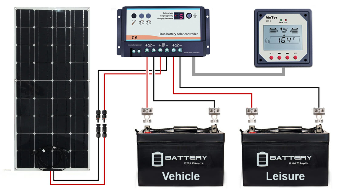
We want to be able to go off grid if needed and not worry about the batteries running flat. Also, we would love to eventually get a compressor fridge which runs off the 12v leisure battery. (We don't like running the current fridge on gas all the time). There are many articles online on howContinue reading "Installing a solar panel and controller"
Trailing Arm Bushing Replacement

Join me on a journey tackling one of the T25's notoriously difficult areas - the trailing arms. Sparks fly whilst I remove hub nuts, disconnect brake lines, snap bleed nipples and meet the tin worm. If your bolts are seized like mine, I recommend using a power saw to cut them off. I used anContinue reading "Trailing Arm Bushing Replacement"
Truck Mirror Upgrade
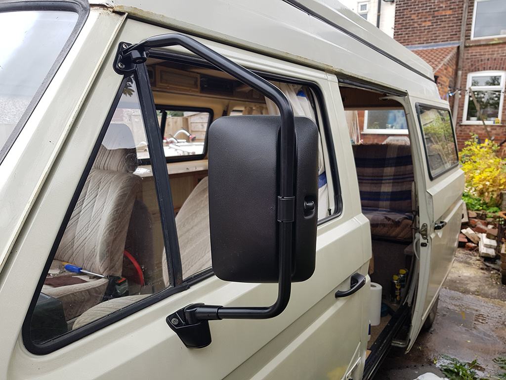
I've always found the standard mirrors to have really poor visibility and tend to suffer from "floppy mirror syndrome" when on the motorway (there are ways to reduce this). I swapped the right side one to a convex mirror type on the drivers side which did improve visibility, however I have always liked the "SyncroContinue reading "Truck Mirror Upgrade"
ARB and Drop Link Bush Replacement

After completing the Lower Control Arm and Radius Rod bushes, the next part of the front end rebuild is the Anti Roll Bar (ARB) and Drop Link bushings. (Also known as Sway Bar and End Links). Again, i'm fitting Powerflex bushings in the video but the approach would be the same for standard replacement bushes.Continue reading "ARB and Drop Link Bush Replacement"
Windscreen Washer Jet Upgrade
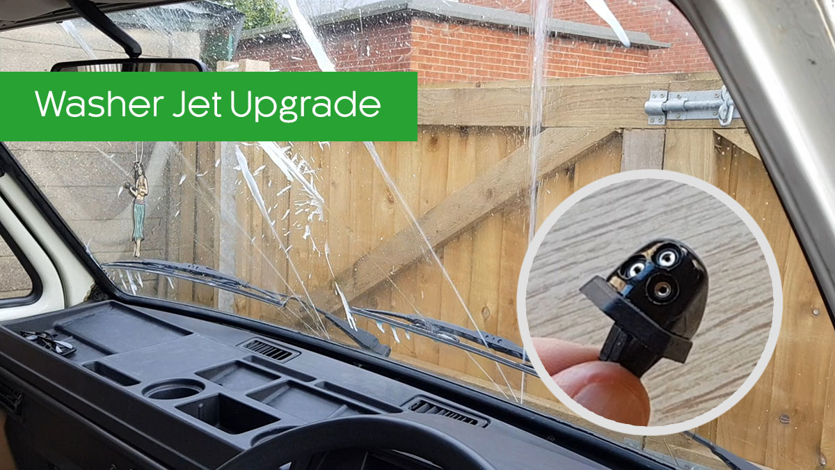
The standard single-jet windscreen washers are really not up to covering the large window sizes on a VW T25. A simple upgrade delivers 200% more fluid through three independent jets - clearing your windscreen much faster and acting like a modern vehicle. This upgrade uses jets from Suzuki Swift/Alto/SX4 cars, reproductions of which are available toContinue reading "Windscreen Washer Jet Upgrade"
Radius Rod Bush Replacement

The next stage renewing the front suspension is the Radius Rods. With a quick look under the van I could see the bushings needed replacing. Like mine, most vans will probably still have the ones originally fitted in the factory. There are some pictures of split bushings, worn radius rods and damaged mount points fromContinue reading "Radius Rod Bush Replacement"
Lower Control Arm Bush Replacement

It's time to look at the front suspension and replace my tired bushes! First on the list (thanks to a group buy discount) is the Lower Control Arm (also known as Track Control Arm). The diagram below shows the bush (pink) and the Lower Control Arm (orange). On earlier models (pre-1984) the Control Arm andContinue reading "Lower Control Arm Bush Replacement"
Rust Treatment

There was no way the van was going to pass it's next MOT with some of the rust areas so it was time to treat them accordingly. For small areas I removed as much flaking rust as possible, wire brushed, coated with Bilt Hamber Hydrate 80, filled and then painted. The major repair areas were welded by John atContinue reading "Rust Treatment"
Pierburg 2E3 Disassembly

I recently bought a job lot of parts which included a broken Pierburg 2E3 carburettor. To improve my own knowledge and help others who want to understand the inner workings I have filmed the process of stripping the carb down completely, ready for a rebuild. https://www.youtube.com/watch?v=VKD6ci8o06w
Powerflex Steering Rack Mount Kit

The steering in the van fees a little unresponsive and light at high speeds. I heard that replacing the steering rack bushes can make a huge difference so bought the Powerflex Steering Rack Mount Kit from Brickwerks. I asked for new nuts and bolts in case the originals get damaged and these were included forContinue reading "Powerflex Steering Rack Mount Kit"
Pierburg 2E3 Rebuild and Adjustments

I wanted to do a complete rebuild of the Pierburg 2E3 carburettor on the van to make sure it's running as it should. Coming at this as a complete novice (and worrying i'd damage my good carb) I decided to buy a second unit off eBay so I could learn how it all works. In the following videoContinue reading "Pierburg 2E3 Rebuild and Adjustments"
Removing Autosleeper interior units

With an impending MOT due in September it was time to address the rust issues in the van. The worst area was the offside sill behind the fridge and the only way to access this area is to remove all the interior units. I followed JonathanR's excellent thread on the Club 80-90 forum detailing how he removed theContinue reading "Removing Autosleeper interior units"
Headlight Warning Buzzer
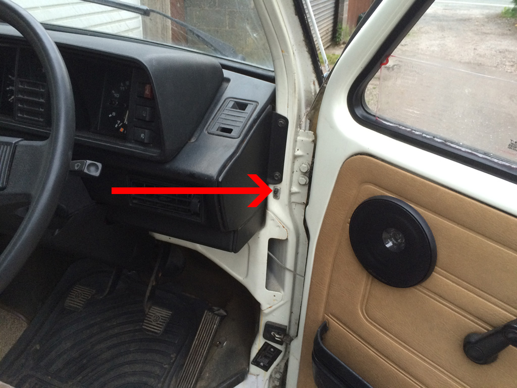
Something I really miss from modern cars is a beep telling me i've left the headlights on when I open the door. As we'll be venturing further and further afield, anything to prevent a dead starter battery in the middle of nowhere is a definite bonus. Luckily, the T25 has everything ready for this easy lowContinue reading "Headlight Warning Buzzer"
Switchable USB Socket

Now that the lighter socket runs off the leisure battery I wanted to swap it with a dual USB socket with a switch to turn it on and off. Neither of us smoke so a USB version would be far more useful than the original socket for powering our phones/sat nav. I went for a Blue Sea Dual USBContinue reading "Switchable USB Socket"
Short Shift Kit

After sorting out the issues with the gear lever and linkage I wanted to install a Short Shift Kit (also know as a Quickshift kit). The kit reduces the gear lever throw by 30%, making gear changes feel much tighter. Several places sell the kit online but I went direct to Si Whitmore at T3volution who makesContinue reading "Short Shift Kit"
Rewiring Stereo to Leisure Battery

My investigation into the Zig MC-2000 12V wiring found that the stereo, lighter socket, courtesy lights and clock run off the vehicle (starter) battery. This seems silly considering the van has a 90AH Leisure battery fitted. I want to use the stereo and socket (to charge devices) when camping without worrying whether the van will start the next day. Research AContinue reading "Rewiring Stereo to Leisure Battery"
