We want to be able to go off grid if needed and not worry about the batteries running flat. Also, we would love to eventually get a compressor fridge which runs off the 12v leisure battery. (We don’t like running the current fridge on gas all the time).
There are many articles online on how to calculate the size of panel you should get. We decided on a 120 watt flexible panel which should suit our needs.
Sir Adventure is an Autosleeper Trooper with a fibreglass pop-top roof so we went for a flexible panel instead of a rigid one. The roof type we have limits the options for how to mount a solar panel and where to route the cabling.
Note: We did this install in August 2017 so there may be better kit options available now and prices may have changed.
The parts list
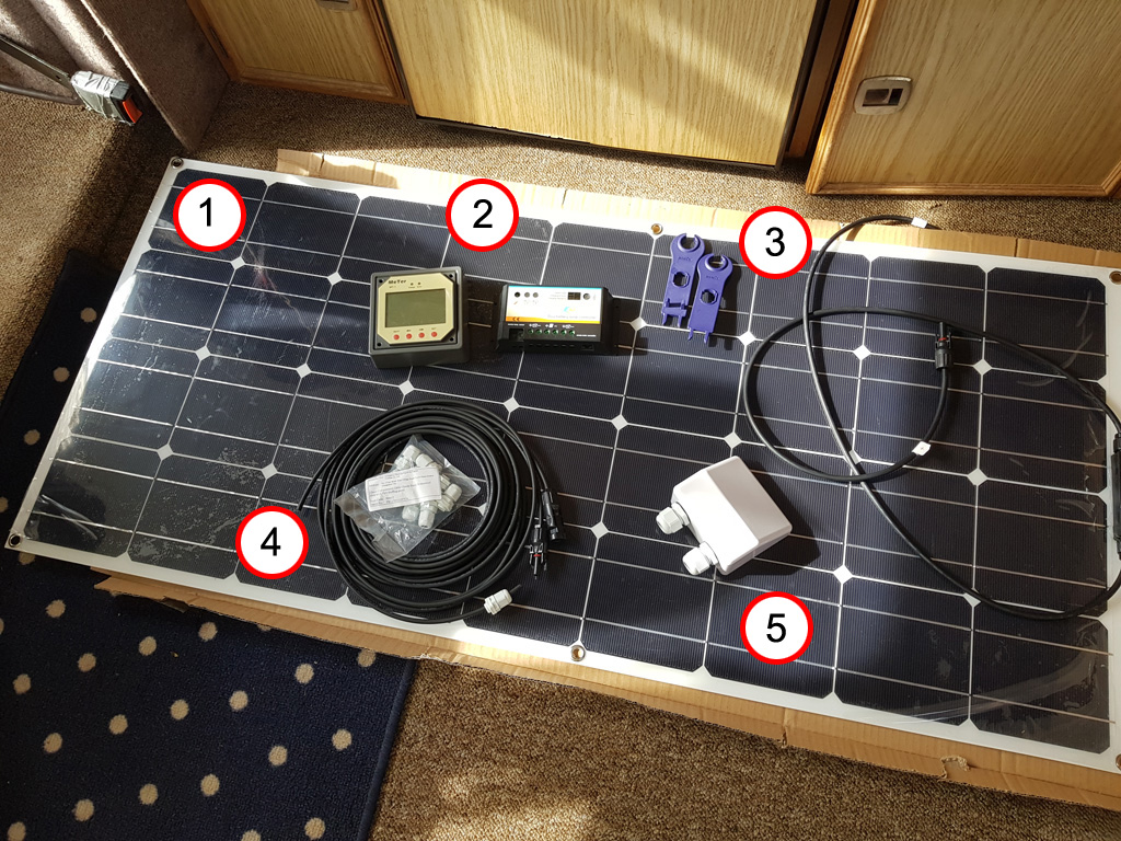
- Elfeland SP-39 12V 120W 1180x540mm Semi Flexible Solar Panel (£82.38)
- 20A Dual Battery Solar Panel Charge Controller with MT-1 Meter (£49.99)
- MC4 Solar Panel Connector Disconnector Tools (£2.99)
- 4mm Cable 2 x 5m Extensions With MC4 Connectors (£12.95)
- Cable Entry Gland – Double (£4.99)
Total: £153.30
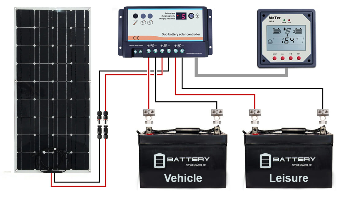
Solar Wiring Diagram
The solar panel connects to the charge controller using 4mm cable with MC4 connectors. The vehicle and leisure batteries then have separate positive (red) and negative (black) 16AWG cable to the controller ports. Finally, the MT-1 display is connected to the controller using an ethernet data cable.

Fitting the panel
The 540mm width of the panel fits perfectly between the length way ribs on the Autosleeper Trooper roof.


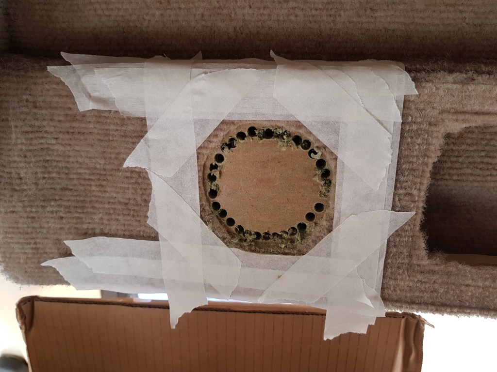
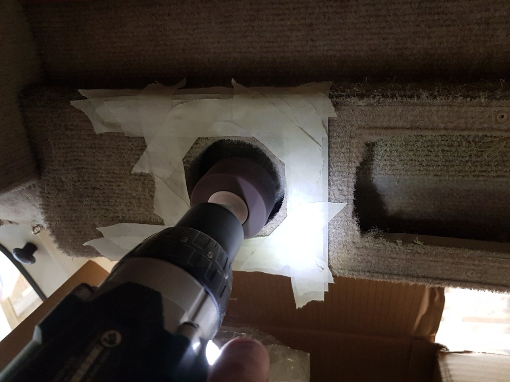
To pass the cable through the roof I needed to drill two holes using a step down drill bit.
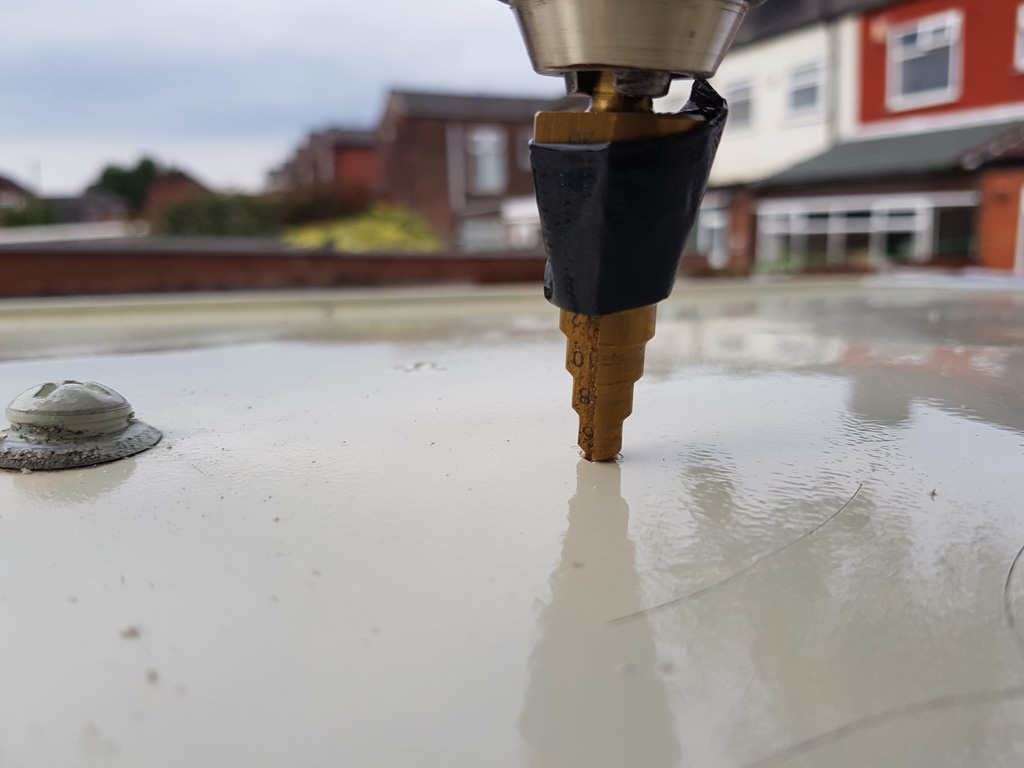
The holes were aligned each side of the wooden support batten and through the headlining.

To route the cable through the roof I used short threaded pipe, nuts and rubber o-rings to make a secure seal.


To secure the panel to the roof I used Sikaflex EBT+ sealant.

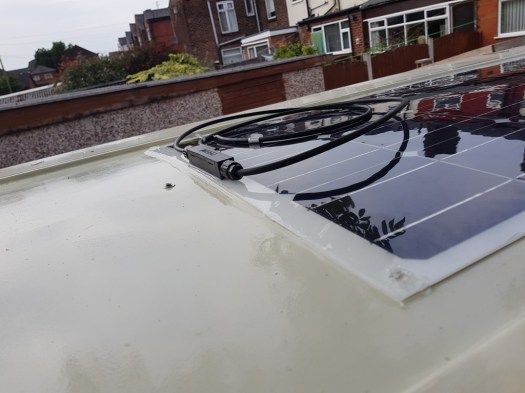
Once set I unscrewed the MC4 connectors and fed the cable through the entry gland. One connector pulled the wiring out of the pin so I had to re-crimp the plug.


The entry gland was then glued down in position. I placed a heavy weight on top to keep the pressure down while it set.

If I did it again I would route the cable across each other, then into the gland. The inflexibility and positioning of the thick cables make them go upwards before entering the gland.
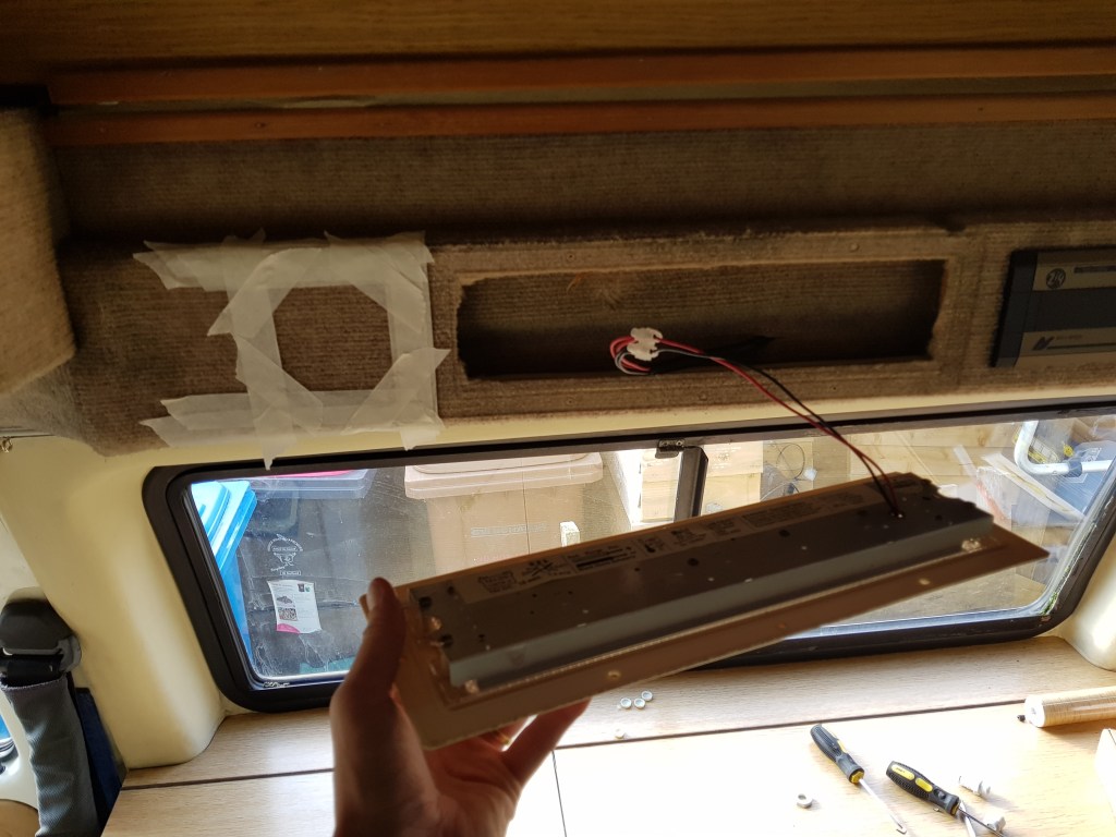
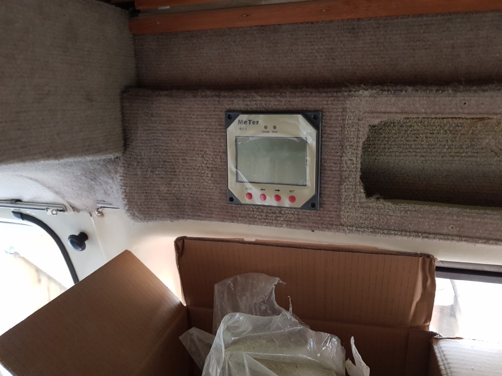
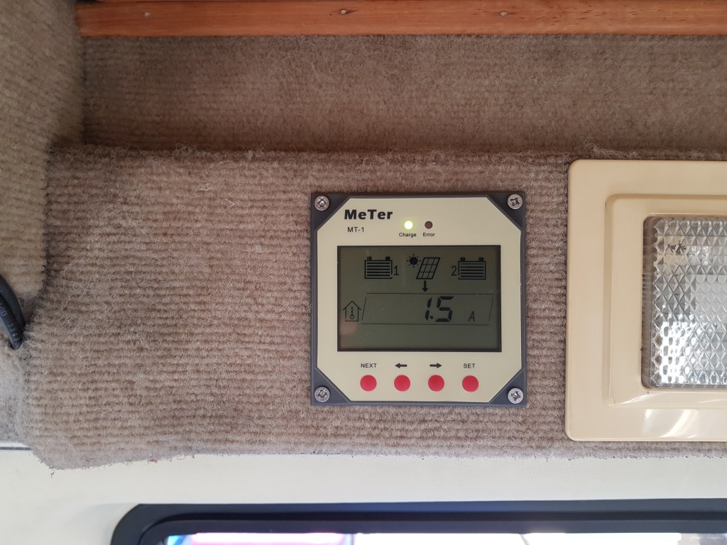
Fitting the MT-1 display
The display connects to the controller and allows you to see lots of information about the solar panel performance and battery health.
I wanted to position it somewhere easy to see so chose a spot next to the interior light. The panel is made of MDF and there is space behind to route the cabling so I could flush mount it.

Routing the interior cables
The Autosleeper Trooper pop-top folds open by pushing the roof upwards and backwards. The side panels then fold outwards to hold the four sides in position. This meant I had to route the cables in a way which did not put them under any stress or get in the way of the hinges.
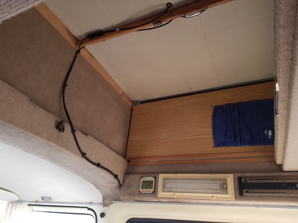
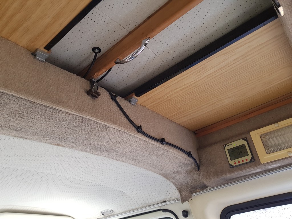
I ran the 4mm cable (from the solar panel) and ethernet cable (from the display) down behind the wall carpet and plastic molding into the bottom of the battery tray behind the drivers seat.
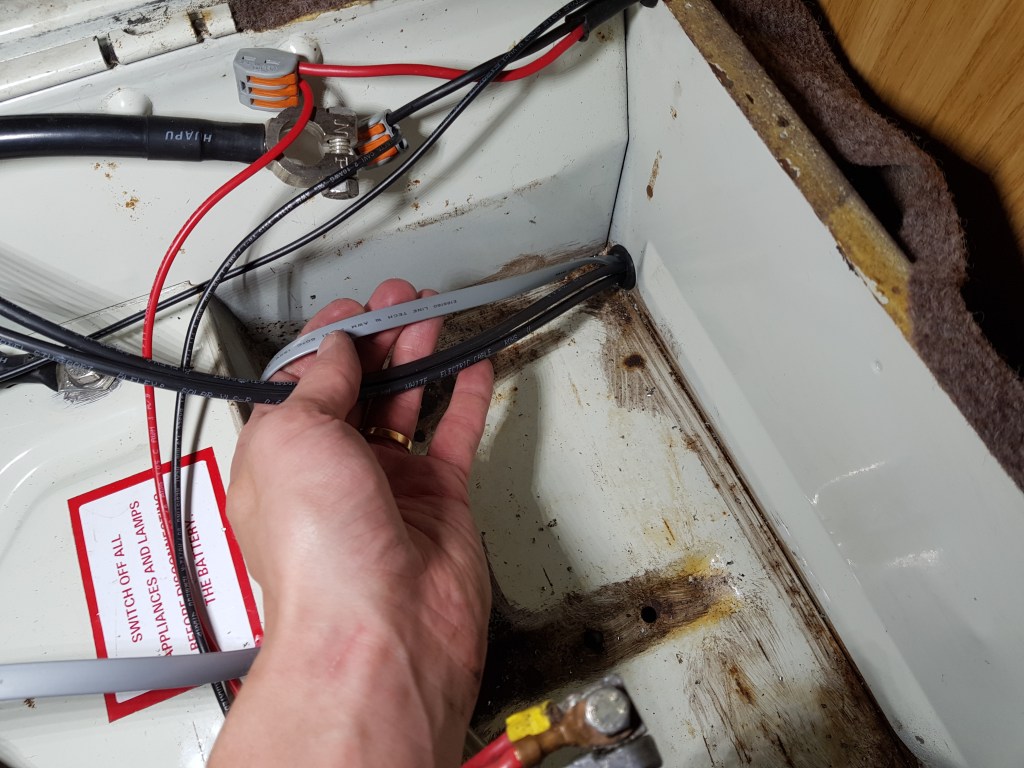
For the leisure battery under the passenger seat, I ran 16AWG cable through the hole just below where the seat belt attaches with a rubber banking plug and routed it under the carpet between the battery boxes.

Everything was then connected up to the charge controller under the driver’s side seat with the batteries back in place.
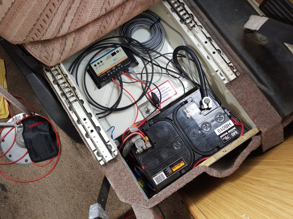
Free electricity!
With everything connected the solar panel automatically collects sunlight and converts it to electricity. Hurrah!
The charge controller manages the status of each of the batteries and automatically stops charging once they have reached capacity. We can now charge our devices, run the interior lights and radio without having to run the engine to top up the battery.
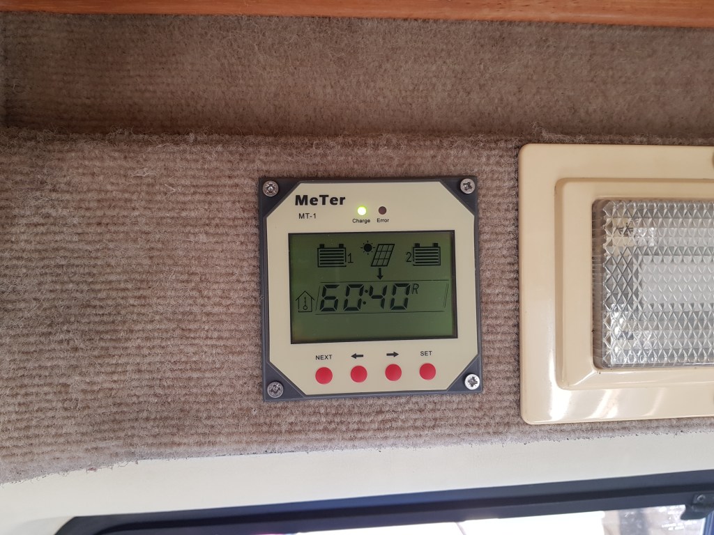
The MT-1 displays both solar voltage and battery voltage as well as charging current and load current. It also show Amp-Hour and Watt-Hour charge accumulation as well as percentage the batteries are charged. There is even a digital clock option to tell the time. Snazzy.
The controller can be set to prioritise a specific battery. I set a 60/40 split between the leisure and vehicle batteries.
Conclusion
It was a fiddly process, especially when routing the cables, but lots of fun working out where everything would go. I really like the MT-1 display to see how the panel and batteries are doing.
I was concerned about buying such a bulky item direct from China but it came well packaged and undamaged. There are many different solar panels out there but this one has stood up to all types of weather.
We’ve had the set up running for three years now and it has worked flawlessly. The batteries are constantly being topped up (even throughout winter) and remain in great health.
If you’re thinking of going solar I highly recommend it. Every time I look at the display I feel i’m helping the environment (in a very specific and limited way).
